
Residual stress affects how certain metals can behave in a magnetic field, which is a primary concern for EV manufacturers who rely on electrical steel for motor cores. When residual stress is uniform in electrical steel, this results in higher motor efficiency. So, it’s critical that engineers are able to confirm the exact amount of residual stress in the cores.
Various measurement techniques have been developed over the years, but most are destructive or inaccurate. What EV manufacturers need is a robust, accurate, repeatable, and non-destructive technology.
Table of Contents
How Residual Stresses Impact Electrical Steel
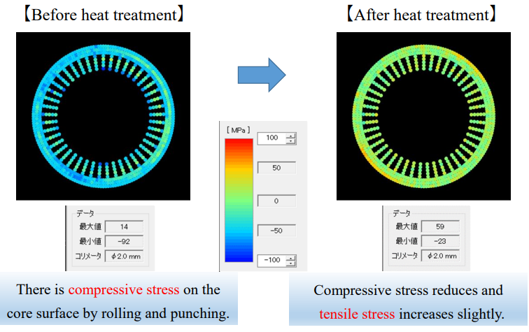
Magnetic Effects
The crystal structure of ferrous metal has a strong influence on how it responds to magnetic flux. This is especially true when the iron is alloyed with a small quantity of silicon to create electrical steel. Silicon increases magnetic permeability (the ability of a metal to concentrate or support the formation of a magnetic field) and reduces core losses.
For background, core losses can be thought of as magnetic friction. They result from delays in how the magnetic poles within the metal crystals move in response to changing magnetic flux (hysteresis) and the formation of eddy currents.
Residual stress in electrical steel correlates with the density of dislocations in the atomic structure. This impedes the ability of the magnetic poles to move, increasing magnetic friction, which shows up as lower permeability and higher core losses.
Mechanical Distortion
Residual stresses can warp or distort electrical steel. These physical effects impact the tight stacking and alignment required in motor cores, leading to gaps that increase eddy current losses. Furthermore, areas with high residual stress are more susceptible to mechanical failure under operational leads, potentially leading to premature failure in the motor.
Thermal Effects
Increased core losses can cause more heat generation within the motor, which can degrade insulation materials, reduce magnet performance, and shorten motor lifespan. Operating temperatures can also cause residual stresses to relax unevenly, leading to further distortion or changes in magnetic properties over time.
Methods for Measuring Residual Stress in Electrical Steel
Residual stress can be measured through both destructive and non-destructive methods. The destructive approaches mainly involve fitting strain gauges to the surface, cutting away a small region, and looking at how the material has distorted.
In industrial and commercial environments, there’s a strong preference for non-destructive methods, especially those that don’t require samples to be cut or drilled, as this alters the residual stress.
The three primary non-destructive technologies for measuring residual stress are:
- Barkhausen Noise Analysis (BNA): An acoustic technique that involves listening for the “ping” made by the magnetic domains shifting rapidly when exposed to a magnetic flux.
- Neutron Diffractometry: Involves observing how a crystal structure, such as metal, diffracts an incident stream of neutrons. The stream can penetrate deep into the bulk of the material.
- X-ray Diffraction (XRD): Similar to neutron diffractometry but using X-rays, this application of Bragg’s Law is used to measure residual stress in the near-surface region of a material.
Measurement Challenges
Magnetic Properties
Permeability influences the results obtained from BNA. Barkhausen noise analysis is susceptible to varying magnetic properties in the material, which can result in high noise levels, making it challenging to ensure total measurement accuracy.
Large Grains
The typical grain size of electrical steel is large (around 100 μm), so it isn’t easy to measure with conventional methods, especially X-ray diffraction. Conventional XRD methods assume that a large number of randomly oriented grains are illuminated by the X-ray beam, providing statistically averaged diffraction peaks that are smooth and well-defined.
However, in electrical steel (or other materials with large grain sizes), the X-ray beam can only interact with a few grains or even a single grain within the illuminated area, making it hard to get adequate data, resulting in irregular and spotty patterns rather than smooth peaks that result in inaccurate stress calculations.
Additionally, electrical steels often have strong crystallographic textures, so grains are not randomly oriented, which means that certain orientations will dominate the diffraction pattern. The lack of random orientation also leads to anisotropic diffraction responses, complicating measurement accuracy.
Material Thickness
Electrical steel laminations used to produce motor cores are often very thin (0.2 to 0.35mm/200 to 350 μm) because the thinness helps break up the pathways for eddy currents (reducing the magnitude and its associated losses), reduce hysteresis losses, and improve thermal management, therefore improving motor efficiency. Obtaining accurate residual stress measurements on such materials, even with traditional X-ray diffraction methods, is difficult because penetration and scattering can vary significantly.
Additionally, as laminations get thinner, they become increasingly difficult to handle.
Sensitivity to Heat Treatments
The magnetic properties of electrical steel are highly sensitive to heat treatments, as this affects crystallographic orientation and hinders domain wall motion. Likewise, residual stress is affected by minor changes in the processing environment. Precise control is essential for achieving accurate and repeatable results.
Surface Finish
Rougher surfaces and variations in surface finish affect the measurement of both magnetic properties and residual stress. With X-ray techniques, rougher surfaces (as produced by machining) increase scattering and change penetration depth. They also reduce the accuracy and repeatability of BNA methods. Preparing a smooth surface for XRD with large-grained materials is also challenging because polishing can introduce additional stresses or remove material from certain grains.
Why XRD Is Emerging As a Better Measurement Method
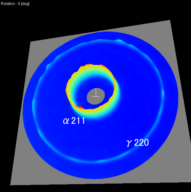
Although there are some challenges with conventional methods, X-ray diffraction is considered the best non-destructive method in terms of accuracy for measuring residual stress in electrical steel. Historically, X-ray diffraction was done using the sin2ψ method, which uses multiple incident angle exposures and a zero- or one-dimension detector to capture the diffracted signal.
In recent years, the cosα method has emerged as a better XRD technology. In this method, a single-incident X-ray beam is detected using a two-dimensional detector. The captured image appears as a series of concentric circular rings referred to as the Debye-Scherrer ring pattern. Analyzing the number, position, and intensity of these rings reveals information about the crystal structure of the material being analyzed.
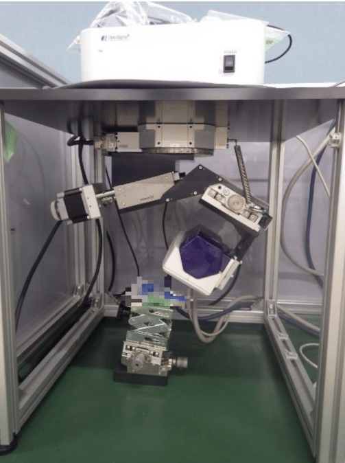
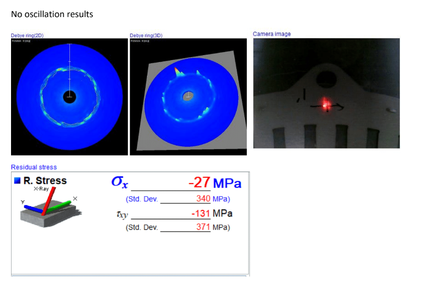
Additionally, tri-axis oscillation, a feature of Pulstec’s XRD analyzer, also helps significantly improve measurement accuracy when analyzing EV motor cores. During oscillation, the X-ray incident angle is changed to X, Y, and θ during exposure. By changing the incident angle, more diffraction can be acquired, so more data can be captured from multiple orientations, averaging out the effects of grain orientation and texture variations.
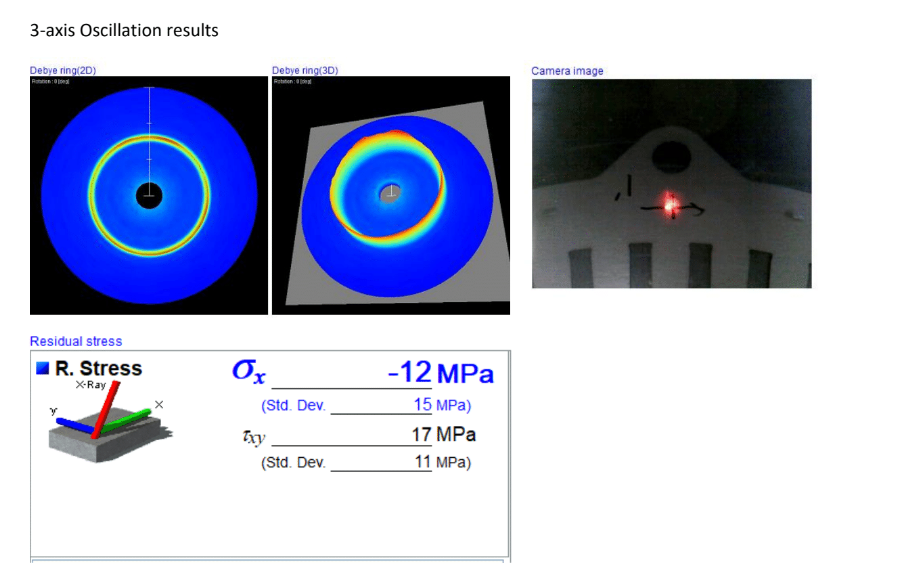
Using Pulsec’s XRD System for Area Mapping
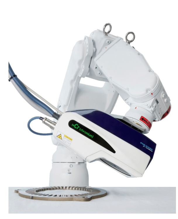
Pulstec was the first company to create a commercially successful X-ray residual stress analyzer using the cosα method, our μ-X360s. This system can non-destructively measure residual stress in 60 seconds and comes with an optional motorized tri-axial stage accessory to allow for tri-axial oscillation during measurement.
Our new robotic residual stress measurement system, which integrates our original μ-X360s XRD analyzer with a robotic arm and 3D laser scanner, also supports 1-axis, 3-axis, or planar slide oscillations. The scanner, attached to the robotic arm, uses the triangulation method to collect data and can ensure measurement stability even on curved or shiny surfaces. This system can also measure areas as large as 300mm x 300mm and supports area mapping, making identifying residual stresses easier. You can read this blog for more information on how to area map with our system.
Learn More Today
Please visit our blog for more residual stress-related resources, or contact us today if you’d like to hear more about our robotic residual stress measurement system or request a free demo.

