As a thermal process, welding creates expansion followed by contraction. However, solidification during cooling locks the welded pieces into a specific geometric relationship before they return to their original dimensions, sometimes resulting in residual stress in weld joints. Additionally, additive manufacturing is a form of welding that suffers from the same problem.
Due to the nature of welding, some amount of residual stress is inevitable, but it can have both positive and negative consequences for joint durability and function. When developing a Welding Procedure Specification, always anticipate residual stress and identify ways to mitigate it.
This blog will review the possible impacts of residual welding stress, identify mitigation methods, and how to measure this stress.
Table of Contents
What Are the Causes of Residual Welding Stress?

Welding involves local melting, followed by fusing and solidification. This creates residual stress in two ways:
- Through thermal expansion and contraction
- As a result of a solid-state phase transformation
Heating during welding causes expansion, followed by contraction, as the welding torch withdraws. Stress only starts to build in the metal after it cools below the solidification temperature and yield strength increases.
When welding steel, heating causes a phase change, forming austenitic structures. These transform to martensite during and after solidification, but the martensite structure occupies a greater volume. This solid-state transformation can continue for some time after welding, adding to the problem.
How These Stresses Impact Components

Residual stresses after welding can be tensile or compressive, depending on the longitudinal and normal distance from the weld. If these stresses exceed the material’s yield strength, they will cause deformation and warping before the welded joint cools completely.
While compressive strength has some benefits, tensile residual stress that’s remaining after cooling can be especially problematic for three reasons:
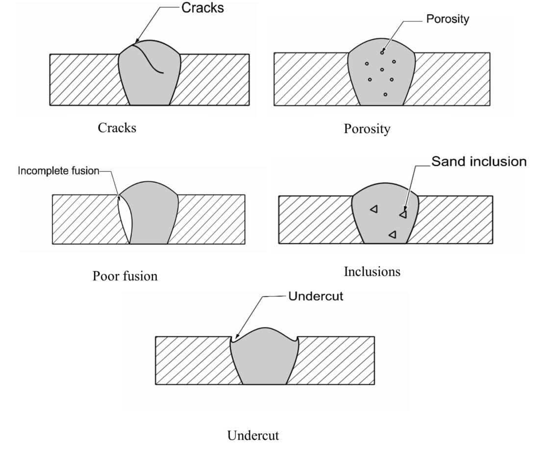
- It causes weld defects, particularly hot and cold cracks and lamellar tearing.
- It reduces the load-bearing ability of the joint.
- It reduces fatigue strength.
As mentioned, compressive residual stress, if present, is usually lower than tensile stress and can be beneficial. This results from its ability to increase the joint’s load-bearing capabilities and improve surface properties. However, it still tends to reduce fatigue strength.
Given time, residual stresses within a welded joint come into balance, usually with the part being distorted from the desired geometry. Subsequent machining removes surface residual stresses and creates new imbalances in those remaining. These are evened out by the part distorting until the net effect becomes zero.
Mitigating These Stresses

Residual stresses resulting from welding can be reduced by:
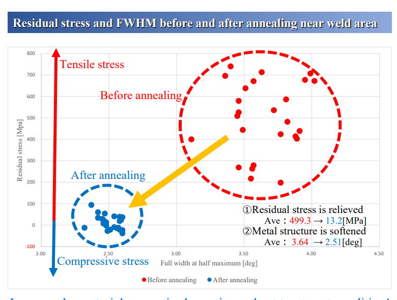
- Preheating: Heating the metal pieces before welding allows them to expand uniformly. This reduces the compressive and subsequent tensile stresses and reduces the tendency of the weld to crack.
- Post-Weld Heat Treatment: Stress-relieving operations, such as post-weld heat treatment and shot-peening, reduce stress in the joint but at the expense of properties like hardness.
- Mechanical Methods: Mechanical methods, like Ultrasonic Impact Treatment (UIT), apply mechanical loads to the surface that form compressive stress. This can reduce levels of tensile stress.
- Optimizing Welding Speed: By putting less heat into the pieces being joined, the magnitude of the problem is reduced. This is done by traversing as quickly as possible while still achieving the desired levels of penetration and fusion.
- Welding Fixture Frame: A fixture frame is used to pre-position the pieces being welded so residual stress pulls them into the required orientations.
Factors to consider when selecting a mitigation method include the type of metal being welded, the geometry of the shape, and the distribution of the residual stress.
A trial-and-error approach is sometimes taken when the job is relatively low value, or the application is not critical. In the case of high-value projects, this is impractical, and it’s not recommended where the weld will be highly loaded. In situations like these, the best way of planning the weld is to determine the orientation and magnitude of the stresses that will result.
Identifying & Calculating Stress

There are several ways to measure residual stress. Each method can be classified as destructive and non-destructive. The destructive group includes:
- Slitting: Slice through the material and observe whether the gap opens up, and if so, by how much.
- Contour Method: Sectioning the weld will result in some “lift” of the upper and lower surfaces as residual stresses act to rebalance themselves. Force this lift down, and the end surface will be displaced, indicating the degree of residual stress.
- Hole Drilling: Attach strain gauges to the surface in a circular pattern at 120-degree intervals, then drill a small hole at the center of the circle. This will create an unbalanced situation where the gauges will indicate how the material attempts to move to compensate.
Non-destructive methods include:
- Neutron Diffraction: This method involves measuring residual stress in materials by analyzing the diffraction patterns created when neutrons interact with a material’s atomic structure. It’s highly effective for investigating internal stresses.
- Barkhausen Noise Analysis: In this method, residual stress is detected by the magnetic noise that’s produced when a magnetic field is applied to a ferromagnetic material. However, it relies on the principle that changes in the magnetic structure of the material, caused by stresses, alter the noise signal.
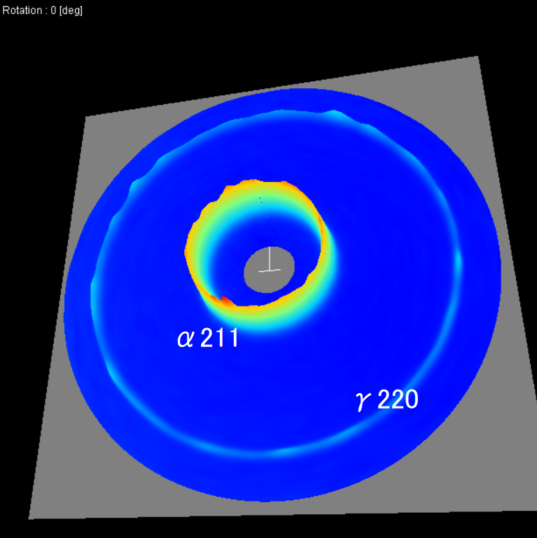
- X-ray Diffraction: X-ray diffraction is by far the most practical non-destructive method for laboratory and industrial measurement of residual stress. It involves directing an energy or particle beam into the metal and observing how it’s diffracted by the crystal lattice. It’s highly repeatable, non-contact, and high-precision. There are primarily two sub-methods of XRD, cosα and sin2𝜓. cosα uses a two-dimensional sensor, which acquires the entire Debye-Scherrer ring. You can read this blog for more information on the differences between these two methods.
When choosing a method, the primary factor should be whether or not the sample material needs to be preserved. If it does, use a non-destructive method. The next factor should be the type of material you’re measuring and its compatibility with the method. For example, neutron diffraction is compatible with materials that allow neutron penetration, like steel, aluminum alloys, and titanium. In contrast, X-ray diffraction is only compatible with crystalline materials where X-rays can be diffracted.
Learn More From Pulstec
Pulstec is an industry-leading manufacturer specializing in engineering innovative X-ray equipment, like our μ-X360s XRD residual stress analyzer. Our analyzer is non-contact and non-destructive and displays residual stress results in 60 seconds.
Contact us today to learn more about our analyzer and request a free demo, or visit our blog for more residual stress resources.

